🚀 Power Your Projects with Precision!
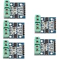
The HiLetgo L9110S DC Motor Drive Module is a compact and efficient controller board designed to drive dual DC motors or 4-wire stepper motors. With a versatile voltage range of 2.5-12V, this lightweight module is perfect for hobbyists and professionals alike, ensuring reliable performance in various applications.
| Manufacturer | HiLetgo |
| Brand | HiLetgo |
| Item Weight | 0.634 ounces |
| Package Dimensions | 4.1 x 3.3 x 0.5 inches |
| Item model number | 3-01-0499 |
| Is Discontinued By Manufacturer | No |
| Color | Blue |
| Material Type | FR4 |
| Size | Small |
| Manufacturer Part Number | 3-01-0499 |
A**R
Dual H-bridge circuit board helps drive 5 volt DC pancake stepper motor
This is probably our third or fourth purchase of these neat stepper motor driver boards. The board is well designed and if you stay within the specifications you can operate low voltage stepper motors that do not require much more that 1/2 of an amp of current. Our pancake bipolar stepper motors require anywhere from 3 to 5 volts in our application. Typically, we run the steppers at 3 volts and have no problems operating the stepper motor driver boards. The circuit boards come individually wrapped, are always shipped the next day , and the boards are very reliable. You can damage the circuit if you try to operate beyond their range of the specs. But, if you stay with the specs and do not reconnect or disconnect the circuit with the power on, the boards will operate well and are very reliable. We have also used these drivers to operate some NEMA 17 steppers that are rated not to exceed 1.3 amps. We can also operate these steppers at 3 volts without any problems. We typically use 3.3 to 6 volt controller pulses for each of the four inputs to the driver to operate the stepper motor driver circuitry.
A**R
These dual H-bridges controlled my NEMA 17 bipolar stepper motor with two 1.5 volt D size dry cells
The dual H - bridges arrived on time and were well packaged. I have a 74194 universal shift register to drive the 4 inputs to the dual H - bridges.In my case I used a 555 timer to generate a clock pulse of 1 Hz to control the 74194. The 4 output pins to the shift register were carefully connected to the dual H - bridge connection terminal block. You have to study your 4 wire connections to the terminal block to get the pulse sequence correct. But, I had done this. Make sure you ground your dual bridge to the 74194 bread board and use two D dry cells to apply 3 volts or so to the dual H - bridge circuits. My NEMA 17 stepper motor worked great with this design and it was great to know that the dual H - bridge circuit boards were well made, well designed and were reliable. I used 4 AA bateries (6 volts) to power my shift register.
B**Y
Had issues trying to use this device.
I needed these to control two motors. However, I had the A side fail on me on one of the modules. I tried connecting a second one, but was more careful. The A side will only work correctly in one direction, when I try and reverse the direction, which is the normal use case for these bridges, it starts to draw way too much current, and will cause the bridge to fail. The B side works correctly in both direction on the two modules I tried.
D**D
Pretty good, basically a board holding the chip
Here is a sort of DIY datasheet: http://me.web2.ncut.edu.tw/ezfiles/39/1039/img/617/L9110_2_CHANNEL_MOTOR_DRIVER.pdfFor more info just search on l9110 motor drivers. I gave them PWM at 10k and they took it but started getting pretty hot when I stepped up from there. I was trying to avoid audio issues and it's best to stay above 20khz but that didn't work out.Here's a bit more on it:The HG7881 (L9110) is a compact motor driver chip that supports a voltage range from 2.5-12V at 800mA of continuous current. These chips have built-in output clamp diodes.Each HG7881 (L9110) chip is able to drive a single DC motor using two digital control inputs. One input is used to select the motor direction while the other is used to control the motor speed. Speed is controlled by using PWM Pulse Width Modulation. Motor drivers typically have what is called a truth table that determines the effect of its inputs. The truth table for a single HG7881 (L9110) chip is as follows:HG7881 (L9110) Truth TableInput OutputIA IB OA IB DescriptionL L L L OffH L H L ForwardL H L H ReverseH H H H OffNote that the actual direction of "forward" and "reverse" depends on how the motors are mounted and wired. You can always change the direction of a motor by reversing its wiring.The HG7881 (L9110) Dual Channel Motor Driver Module uses two of these motor driver chips. Each driver chip is intended to drive one motor, so having two means that this module can control two motors independently. Each motor channel uses the same truth table as above. Each set of screw terminals is used to connect a motor. Refer to the table below for pin header connections.HG7881 (L9110) Dual Channel Motor Driver Module ConnectorPin DescriptionB-IA Motor B Input A (IA)B-IB Motor B Input B (IB)GND GroundVCC Operating Voltage 2.5-12VA-IA Motor A Input A (IA)A-IB Motor A Input B (IB)Recommended using input 1A to control the speed of each motor and input 1B to control the direction.
C**R
Start smoking with 12v
I really like this brand and buy alot of my electronics from them but they messed up on these drivers because the chip will pop & smoke when I add 12v power supply. It works okay when I power it from the arduino uno.
J**.
Great Motor Controller
Easy to get up and running with Arduino, plenty of documentation on how to use. Easy to use and they work. Just follow instructions and the item works as intended.
B**H
Caution ! logic inputs are pulled up to the (12V) input voltage !
Super low cost, so that's great. Being a typical product from SZ, it will be fine AFTER you fix it.Each of the 4 logic inputs are pulled up to the 12V input, that's rude (and might damage) the processor. that run on 3.3 volts and could damage them. just remove the 4ea 10K resistors and you will be fine. Also the red power LED is nice but has a 1K resistor, It is waaay too bright. Replace the 1 K resistor with one of the 10K's that you removed from the inputs for a more reasonable brightness for a power led. If you want to use PWM remove the capacitor that is across each of the outputs. PWM can't drive a capacitor. Better yet reuse the capacitor and add a series resistor like 68ohms in series with it. Google "snubber circuit"
A**R
Needed component for use with an Arduuno Uno
Works as it’s supposed to.
Trustpilot
1 day ago
4 days ago